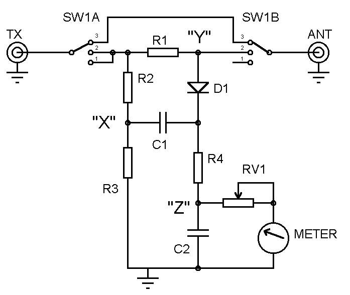
The resistive SWR bridge is highly recommended for both beginners
and experienced constructors.
- It is simple, inexpensive to build, can
be very sensitive and is therefore highly suited for QRP
operation.
- When the bridge is set to position 2
to enable tuning of the Antenna System Matching Unit (ASMU),
the transmitter P.A. stage will always see a lower SWR than
is present at the load. Indeed, if it’s a dead short, or
open circuit the transmitter will only see a 3:1 SWR. Other
complex antenna impedance’s may present a higher SWR to
the antenna socket, but the rig will always see one that
is lower and therefore provide some protection to your P.A.
transistor.
- Because the design relies on using a
resistive bridge, the transmitter output should be limited
by how much power the resistors can safely dissipate. Please
note that inductive (i.e. wire wound) resistors should not
be used.
Ian Keyser G3ROO explains how it works....
|
 |
Considering the following statements
will help with the following explanation:-
- In the interest of simplicity we will assume that the
meter draws no current and there is no phase difference
between points X and Y.
- When RF is applied to the input of the ‘bridge’ the potential
at point X will be at half the total RF potential applied
to the bridge, and this will remain so at all times.
- D1, C1, R4 and C2 form a peak voltage detector. Reading
the potential at point Y in relation to point X.
We will consider three possible scenarios,
- In switch position 1 no load (i.e. antenna) is applied
and so the bridge is now reading the peak RF input voltage
via R1 [50 Ohms], this will have no noticeable effect on
the reading. This position can be used to adjust VR1 for
Full Scale Deflection.
- In switch position 2 and with a load of high impedance
the RF potential at point Y is very nearly the same as the
input RF voltage. In this instance the peak DC voltage at
point Z will be almost half the peak RF voltage applied
(RF volts input - RF Volts/2 [point X]). Alternatively,
if the load impedance is now made very low (say 1 Ohm),
RF volts at point Y is almost zero so the peak detector
will again read about half the RF input voltage - (RF volts
input/2 [point X] - point Y (zero volts [almost]).
Between the above two extremes, if the load impedance is
50 Ohms, the voltage at point Y will now be half input RF
voltage. As now point X and Y are at half RF input voltage
the potential difference between them is zero.
This is the point of 1:1 SWR, and as we deviate from
this ideal, the voltage detected will rise until the two
other scenarios are reached.
- Having tuned the ASMU (with the switch in position 2),
to indicate 1:1 (zero volts), the switch should now be moved
to position 3 to remove the bridge and it will connect the
ASMU directly to the transmitter. To leave it in circuit
in position 2 would divide the R.F power between the antenna
and the resistors in the bridge.
The aspect that catches most out is the fact that the meter
is connected to ground and not to point X.
The reason for this is that as far as the meter is concerned
it is only interested in indicating the DC component. If it
is connected to earth, VR1 has only to be reduced in value
by the value of R3 to give the same reading. In practice,
as VR1 is going to be in the order of kilo ohms compared to
the 51 ohms of R3, this error can be ignored.
Parts List:
RV1 10K, R1/R2/R3 51 Ohm (2W), R4 1K (0.5W), C1/2 10nF, D1
OA91 (or similar), Meter 1mA FSD, SW1 2 pole 3 way
|
